FleX-ADC Development Kit
The FleXform-ADC is the world’s first complete development kit for flexible hybrid electronics. The FleXform-ADC is designed for developing and prototyping printed and/or flexible sensors integrated with physically flexible FleX-ICs. The FleXform-ADC provides:
- “Out-of-the-box” proof of FHE feasibility
- User printable area with on-board FleX-ADC™
- Integration Board and Software
- Enables printed device demonstration
- Fully supported by American Semiconductor’s flexible technology integration team for design and manufacturing
FleXform-ADC is currently available. Contact sales@americansemi.com for information.

FleX-ADC
This 2.5V integrated circuit is an 8-bit successive approximation Analog to Digital Converter with 8 input channels. What makes the FleX-ADC different from other analog-to-digital converters is that it is physically flexible just like the underlying substrate. The FleX-ADC is manufactured in a 190nm CMOS process and then converted to its current flexible format using American Semiconductor’s Semiconductor-on-Polymer technology.

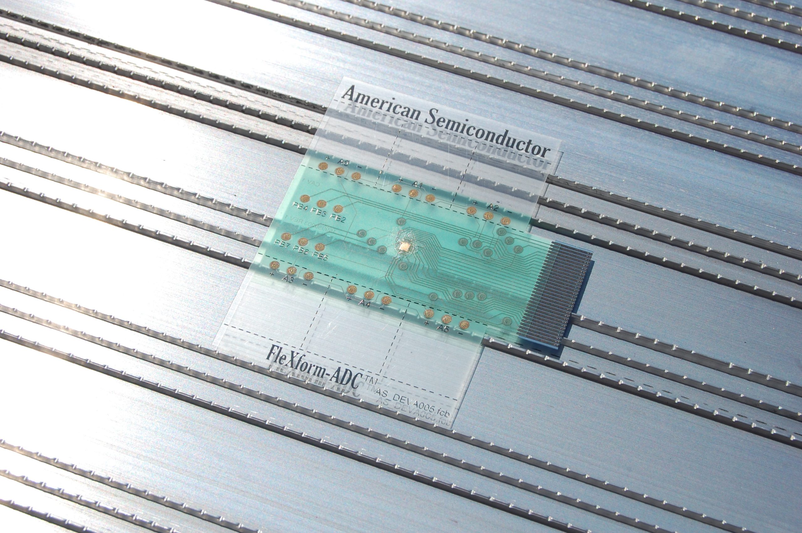
FleXform-ADC Flexible Hybrid System
The substrate for the flexible hybrid system is a two-layer flexible circuit board (FCB). This is a 125 micron (5 mil) thick PET substrate with 2-layers of electronic interconnect created using screen printing techniques. We have also provided means to integrate printed sensors on the flexible circuit board. We have 6 sensor areas available for printing, two of which are connected to Op Amps for signal amplification. The flexible circuit board also provides 6 programmable GPIOs available that can be integrated with your sensors.
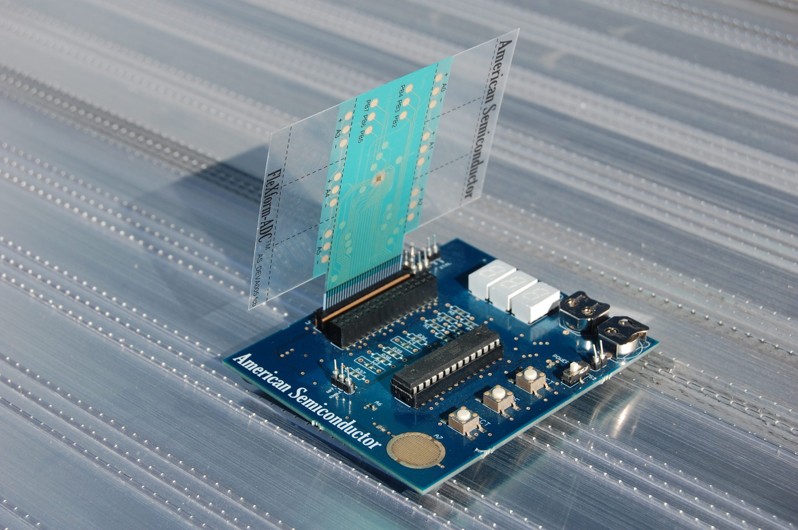
FleXform-ADC PCB
To control and communicate with the FleX-ADC, we have our rigid printed circuit board. The brain of this board is an ATmega328P which you might recognize as the chip used on the Arduino Uno. This chip was chosen so that FleXform-ADC is 99% Arduino compatible. The microcontroller on the PCB comes pre-programmed to let us begin using the development kit right out of the box.
The features of the PCB include:
- 3 Character 7-segment display
- Reset Button
- 2 Programmable, Debounced push buttons
- A breakout connector for the ZIF tail
- Jumpers for Voltage Reference, External Voltage, and Op Amp selection
- A power switch and indicator light
- A Quad Op Amp IC
- Two built in sensors; A thermistor and a skin resistive sensor